BIM MODELING
DESIGN SERVICES PLUS INCORPORATED
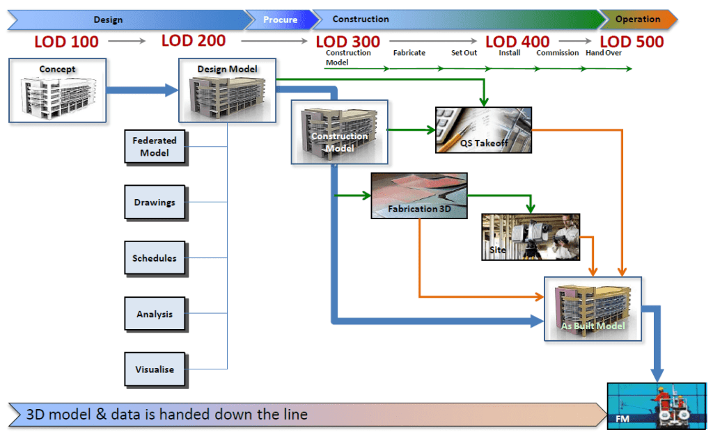
LOD 100-Conceptual
The Model Element may be graphically represented in the Model with a symbol or other generic representation. Information related to the Model Element can be derived from other Model Elements. Any information derived from LOD 100 elements must be considered approximate.
LOD 200 - Approximate Geometry
The Model Element is graphically represented within the Model as a generic system, object, or assembly with approximate quantities, size, shape, location, and orientation. Any information derived from LOD 200 elements must be considered approximate.
LOD 300-Precise Geometry
The Model Element is graphically represented within the Model as a specific system, object or assembly in terms of quantity, size, shape, location, and orientation. Non-graphic information may also be attached to the Model Element. The project origin is defined and the element is located accurately with respect to the project origin.
LOD 350 - Precise Geometry with Connections
LOD 350 The Model Element is graphically represented within the Model as a specific system, object, or assembly in terms of quantity, size, shape, location, orientation, and interfaces with other building systems. Non-graphic information may also be attached to the Model Element.
LOD 400- Fabrication-ready Geometry
LOD 400 The Model Element is graphically represented within the Model as a specific system, object or assembly in terms of size, shape, location, quantity, and orientation with detailing, fabrication, assembly, and installation information. Non-graphic information may also be attached to the Model Element.
LOD 500 - Operational/As-built Models
LOD 500 The Model Element is a field verified representation in terms of size, shape, location, quantity, and orientation. Non-graphic information may also be attached to the Model Elements.
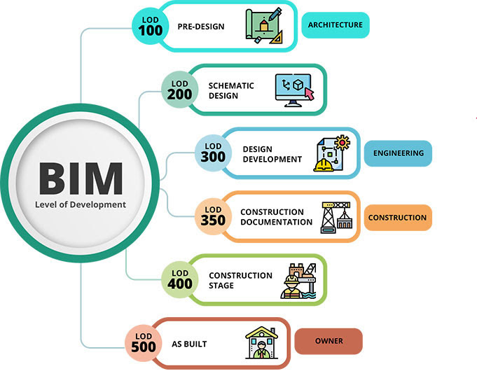
WHAT IS LOD?
FUNDAMENTAL LOD DEFINITIONS
LOD 100 – Concept Design
The building 3D model is developed to represent the information on basic level. Thereby, only conceptual model creation is possible in this stage. Parameters like area, height, volume, location and orientation are defined.
The Model Elements may be graphically represented in the Model with a symbol or other generic representation, but does not satisfy the requirements for LOD 200. Information related to the Model Element (i.e. cost per square foot, tonnage of HVAC, etc.) can be derived from other Model Elements.
Basically, LOD 100 elements are not geometric representations. Examples are information attached to other model elements or symbols showing the existence of a component but not its shape, size, or precise location. Any information derived from LOD 100 elements must be considered approximate.
LOD 200 – Schematic Design
A general model where elements are modelled with approximate quantities, size, shape, location and orientation. We can also attach non- geometric information to the model elements.
The Model Element is graphically represented within the Model as a generic system, object, or assembly with approximate quantities, size, shape, location, and orientation. Non-graphic information may also be attached to the Model Element.
Basically, at this LOD elements are generic placeholders. They may be recognizable as the components they represent, or they may be volumes for space reservation. Any information derived from LOD 200 elements must be considered approximate.
LOD 300 – Detailed Design
Accurate modelling and shop drawings where elements are defined with specific assemblies, precise quantity, size, shape, location and orientation. Here too we can attach non- geometric information to the model elements.
The Model Element is graphically represented within the Model as a specific system, object or assembly in terms of quantity, size, shape, location, and orientation. Non-graphic information may also be attached to the Model Element.
Basically, the quantity, size, shape, location, and orientation of the element as designed can be measured directly from the model without referring to non-modelled information such as notes or dimension call-outs. The project origin is defined and the element is located accurately with respect to the project origin.
LOD 350 – Construction Documentation
LOD 350 includes model detail and element that represent how building elements interface with various systems and other building elements with graphics and written definitions.
The Model Element is graphically represented within the Model as a specific system, object, or assembly in terms of quantity, size, shape, location, orientation, and interfaces with other building systems. Non-graphic information may also be attached to the Model Element.
Basically, the parts necessary for coordination of the element with nearby or attached elements are modelled. These parts will include such items as supports and connections. The quantity, size, shape, location, and orientation of the element as designed can be measured directly from the model without referring to non-modelled information such as notes or dimension call-outs.
LOD 400 – Fabrication and Assembly
Model elements are modelled as specific assemblies, with complete fabrication, assembly, and detailing information in addition to precise quantity, size, shape, location and orientation. Non- geometric information to the model elements can also be attached.
The Model Element is graphically represented within the Model as a specific system, object or assembly in terms of size, shape, location, quantity, and orientation with detailing, fabrication, assembly, and installation information. Non-graphic information may also be attached to the Model Element.
Basically, an LOD 400 element is modelled at sufficient detail and accuracy for fabrication of the represented component. The quantity, size, shape, location, and orientation of the element as designed can be measured directly from the model without referring to non-modelled information such as notes or dimension call-outs.
LOD 500 – As Built
Elements are modelled as constructed assemblies for Maintenance and Operations. In addition to actual and accurate in size, shape, location, quantity, and orientation, non-geometric information is attached to modelled elements.
The Model Element is a field verified representation in terms of size, shape, location, quantity, and orientation. Non-graphic information may also be attached to the Model Elements.
Basically, LOD 500 relates to field verification and is not an indication of progression to a higher level of model element geometry or non-graphic information, it is simply an As-Built model.